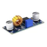
SKU: OT2004-A113 Artikelnummer: AA270 EAN: 8179262862427

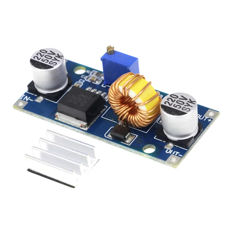
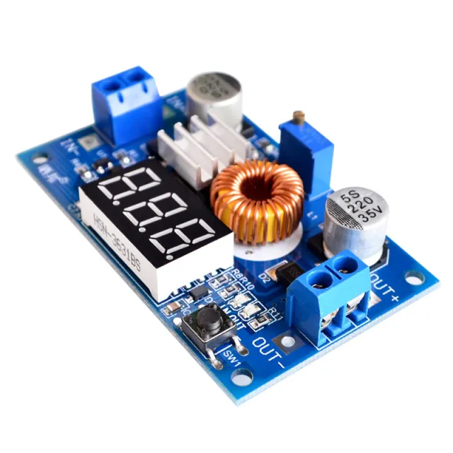
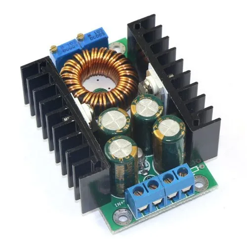
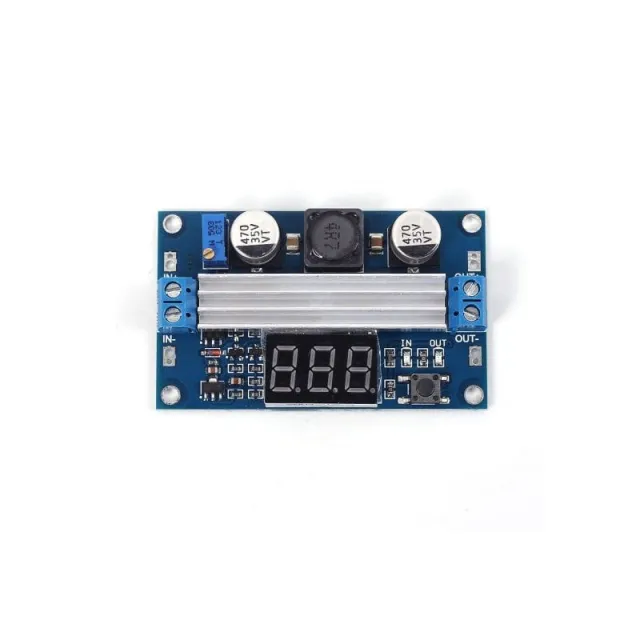
4-38VDC ingångsspänning
1.25-36VDC utgångsspänning, justerbar
0-5A utgångseffekt, med kortslutningsskydd för utgången.
Maximal utgång 75W med termiskt skydd
Inklusive kylfläns som levereras omonterad. Kan fästas med medföljande 3M-tejp.
Mått
Längd: 5,4cm
Bredd: 2,45cm
Höjd: 1,7cm
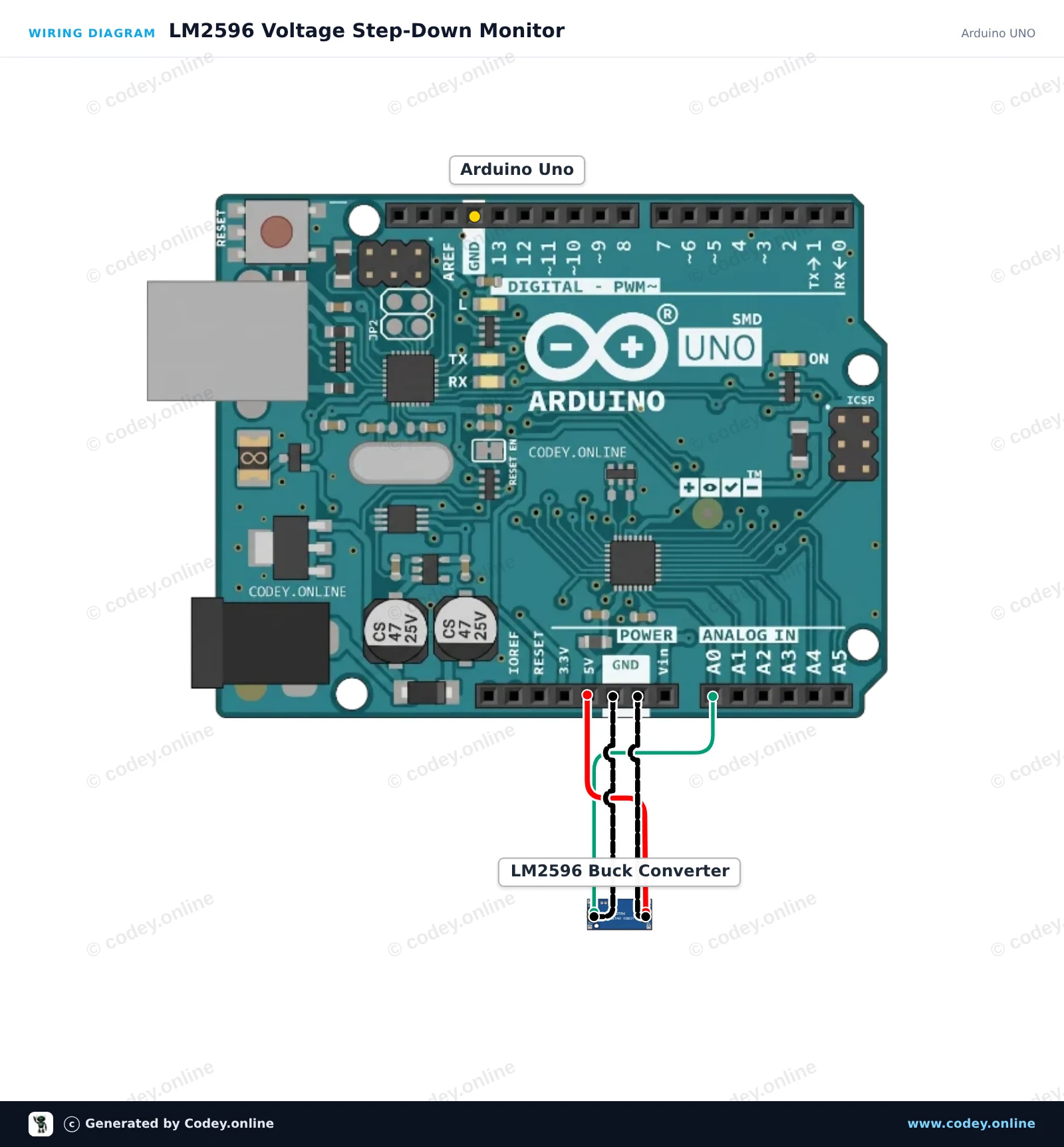
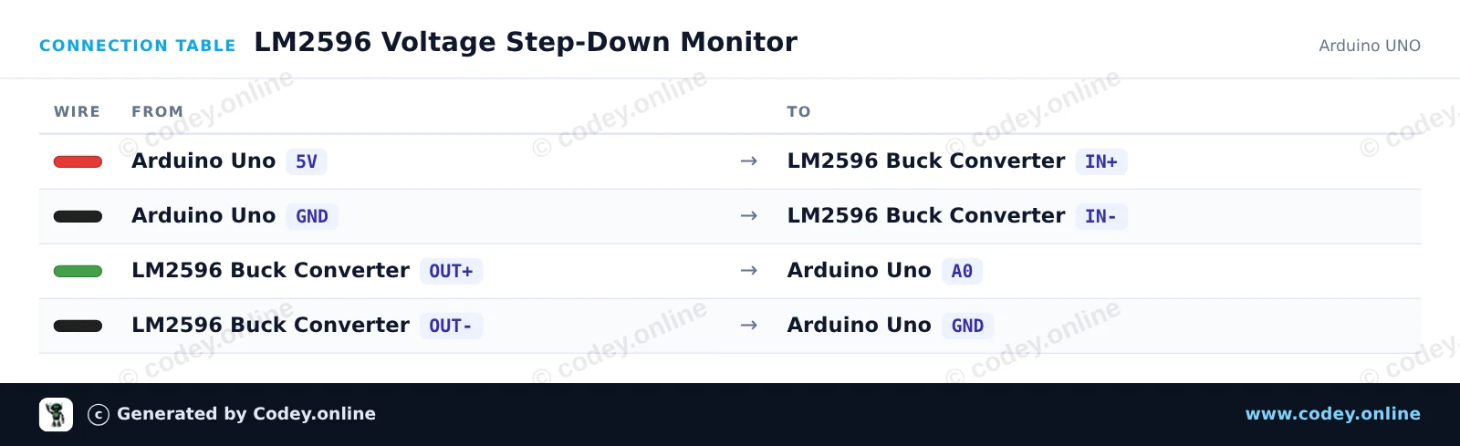
Så här kopplar du Justerbar Step-down-modul 4~38V 5A 96% Hög effektivitet XL4015 till en Arduino UNO eller ESP32, med ett exempelsketch som du kan ladda upp direkt.
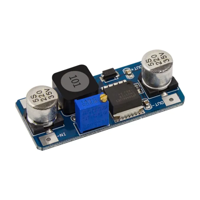
This project powers the LM2596 step-down module from the Arduino 5V rail and measures its regulated output voltage on analog pin A0. Adjust the onboard potentiometer with a small screwdriver to observe the real-time voltage changes printed to the Serial Monitor (keep output under 5V).
/*
 * ==================================================================
 *  Generated by Codey.online  —  https://www.codey.online
 * ==================================================================
 *  Project   : LM2596 Voltage Step-Down Monitor
 *  Board     : Arduino UNO (arduino:avr:uno)
 *  Parts     : Adjustable Step-down Module 3-40VDC 1.5-35VDC LM2596
 *  Libraries : none (built-in)
 *
 *  Codey Online is an AI-powered browser IDE for Arduino and ESP32.
 *  Describe your project and Codey writes the code, draws the wiring
 *  diagram and uploads it to your board, straight from the browser.
 *  This code is free to use, modify and share, without warranty.
 * ==================================================================
 */

const int voltagePin = A0;

void setup() {
  Serial.begin(115200);
  while (!Serial) {
    ; // Wait for serial port to connect
  }
  Serial.println(F("LM2596 Step-Down Voltage Monitor"));
  Serial.println(F("Turn the onboard trimmer to adjust the output voltage (0-5V)."));
}

void loop() {
  int rawValue = analogRead(voltagePin);
  float voltage = rawValue * (5.0 / 1023.0);

  Serial.print(F("ADC Value: "));
  Serial.print(rawValue);
  Serial.print(F(" | Output Voltage: "));
  Serial.print(voltage, 2);
  Serial.println(F(" V"));

  delay(500);
}Wiring diagram and example code generated by Codey.online — https://www.codey.online
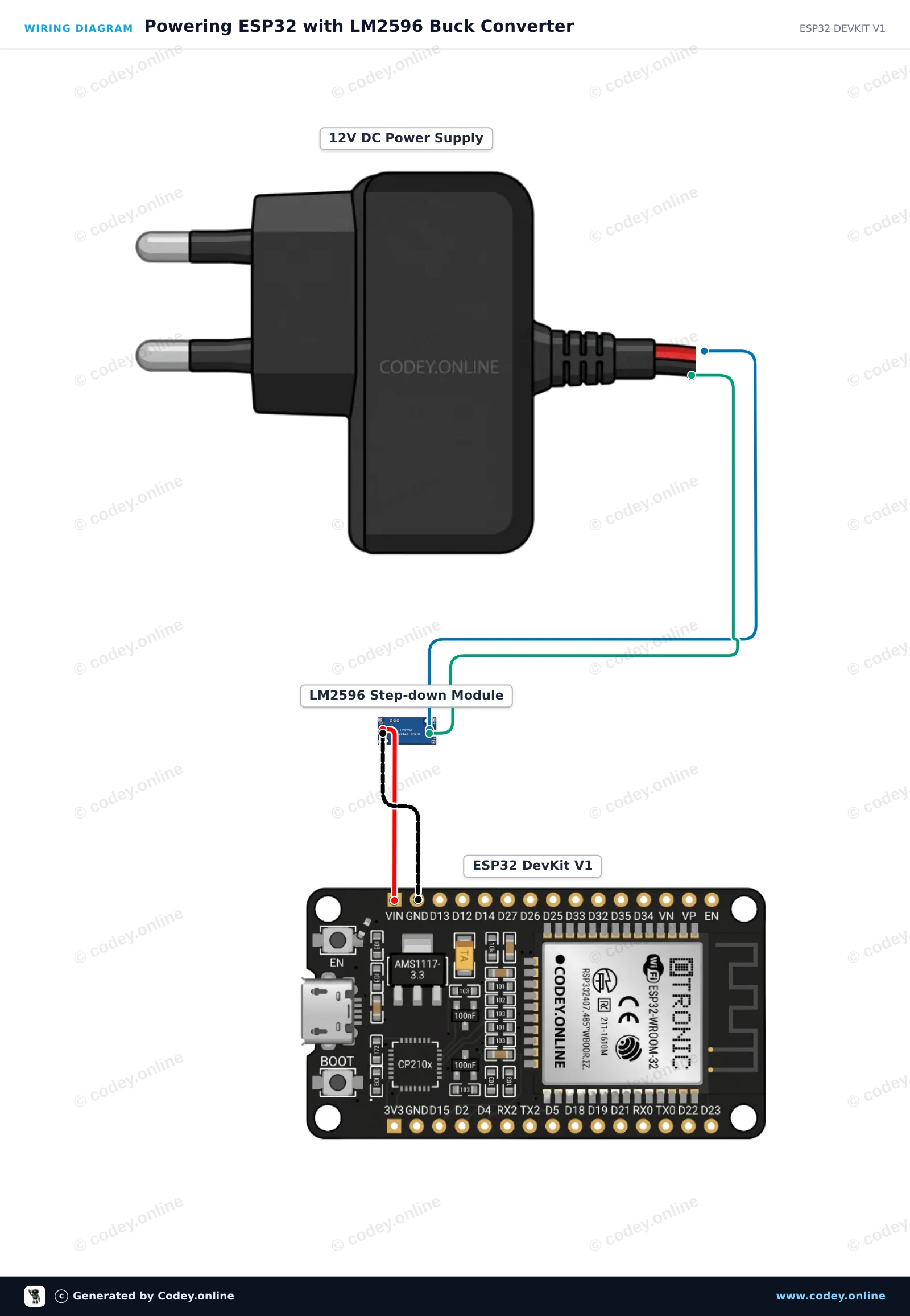
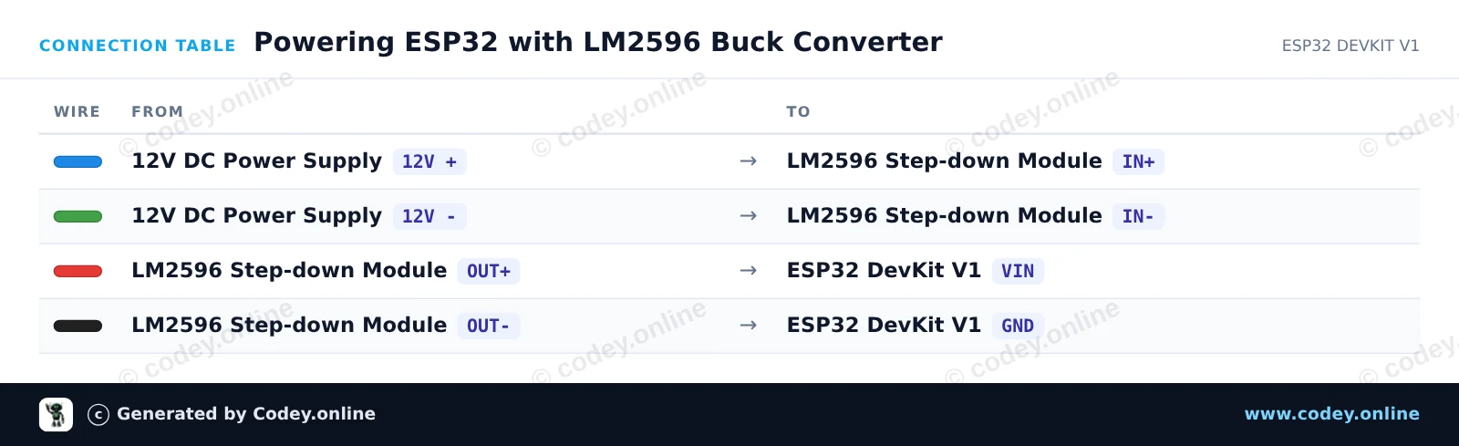
Before connecting the ESP32, use a multimeter to adjust the LM2596 trimmer potentiometer until OUT+ reads exactly 5.0V. The module efficiently steps down the 12V input to a stable 5V output to power the ESP32 via VIN and GND. When connected, the ESP32 boots up, blinks its onboard status LED, and outputs heartbeat messages via Serial.
/*
 * ==================================================================
 *  Generated by Codey.online  —  https://www.codey.online
 * ==================================================================
 *  Project   : Powering ESP32 with LM2596 Buck Converter
 *  Board     : ESP32 DEVKIT V1 (esp32:esp32:esp32doit-devkit-v1)
 *  Parts     : Adjustable Step-down Module 3-40VDC 1.5-35VDC LM2596
 *  Libraries : none (built-in)
 *
 *  Codey Online is an AI-powered browser IDE for Arduino and ESP32.
 *  Describe your project and Codey writes the code, draws the wiring
 *  diagram and uploads it to your board, straight from the browser.
 *  This code is free to use, modify and share, without warranty.
 * ==================================================================
 */

// LM2596 Step-Down Buck Converter ESP32 Power Demo
// Note: Always adjust LM2596 output to 5V before connecting to VIN!

const int LED_PIN = 2; // Onboard LED

void setup() {
  Serial.begin(115200);
  pinMode(LED_PIN, OUTPUT);

  Serial.println("LM2596 Step-Down Buck Converter Demo");
  Serial.println("ESP32 successfully running on regulated 5V power!");
}

void loop() {
  // Turn LED on
  digitalWrite(LED_PIN, HIGH);
  Serial.print("Uptime: ");
  Serial.print(millis() / 1000);
  Serial.println(" s | Power Status: OK (LED ON)");
  delay(500);

  // Turn LED off
  digitalWrite(LED_PIN, LOW);
  delay(500);
}Wiring diagram and example code generated by Codey.online — https://www.codey.online






 English
  Nederlands
  Frans
Frans  Deutsch
  Italiano
  Español
  Suomi
Suomi  Polski
  Dansk
Dansk  Ελληνικά
  Български
  Čeština
  Hrvatski
  Aileen