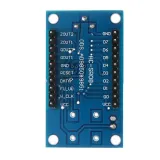
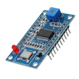
SKU: OT3459 Artikelnummer: NA416 EAN: 8720618690838

Signalgeneratorer/funktionsgeneratorer är superpraktiska från RF till inbyggd logik, men de är oftast inte superbilliga.
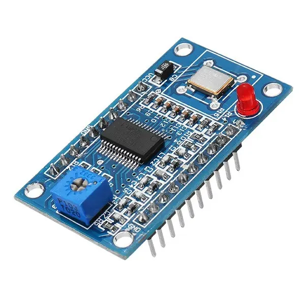
God nyhet: med denna AD9850 DDS-modul kan du med lite montering skapa din egen flexibla, funktionella och användarvänliga Arduino-frekvensgenerator!
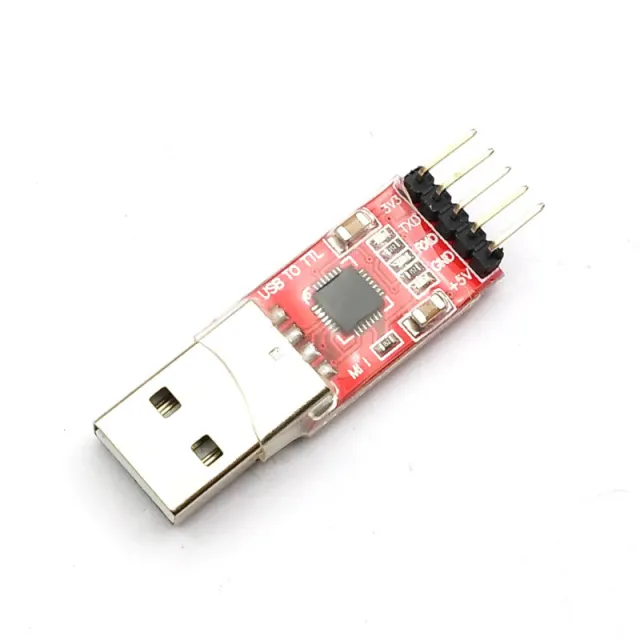
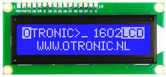
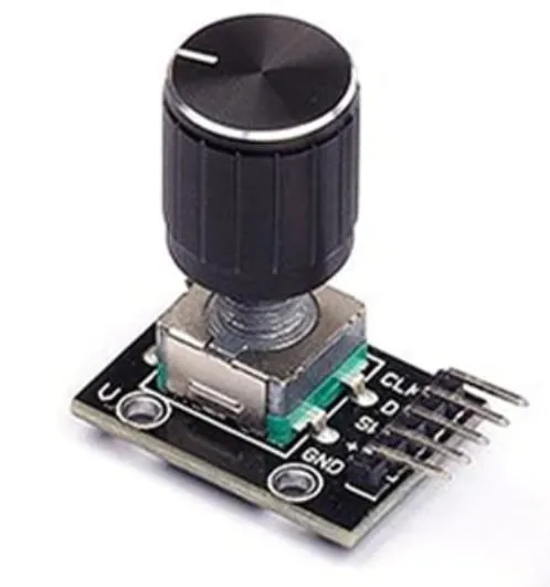
Med en LED-display, roterande potentiometer och en Arduino kan du göra en lättanvänd, fristående signalgenerator. (Glöm då inte att skaffa en CP2102 USB till TTL Serial Converter om du inte redan har en hemma)
Du kan också välja att endast kombinera den med Arduino Uno på ett breadboard.
En helt annan väg är att använda denna modul för att skapa din egen Software Defined Radio (SDR).
Sammanfattningsvis, en fin modul att börja arbeta med!
Egenskaper:
ANVÄNDNINGSOMRÅDEN:
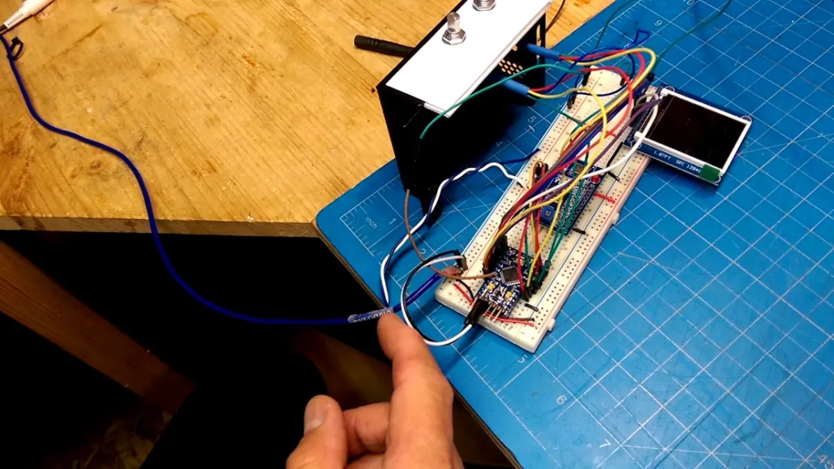
Vid uppspelning laddas videon från YouTube.
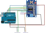
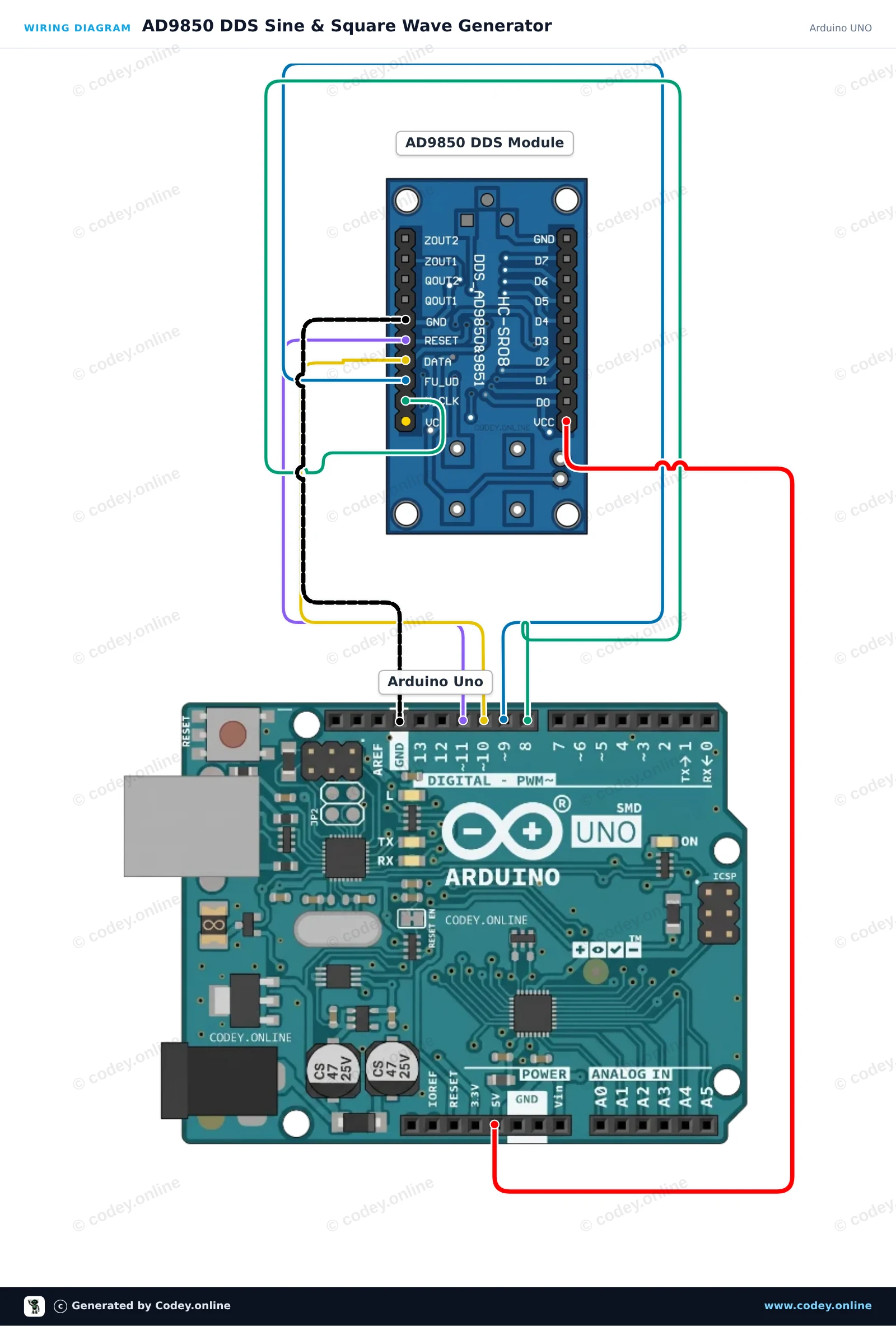
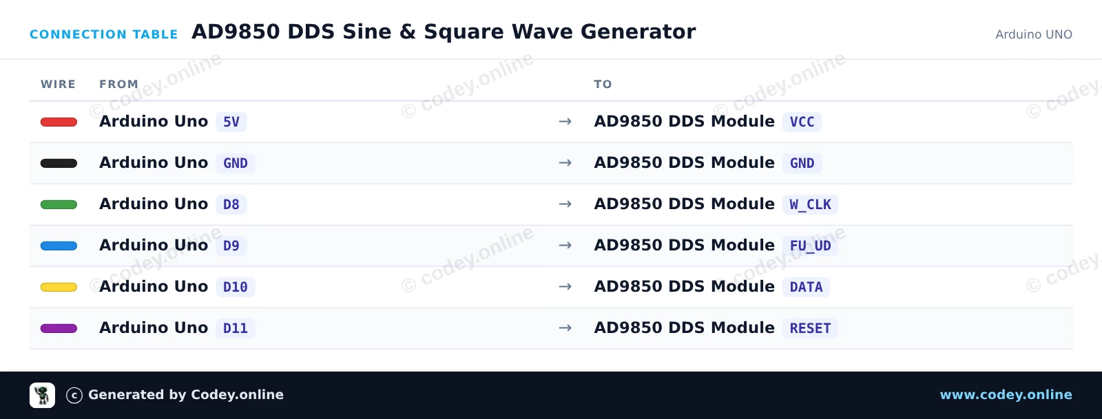
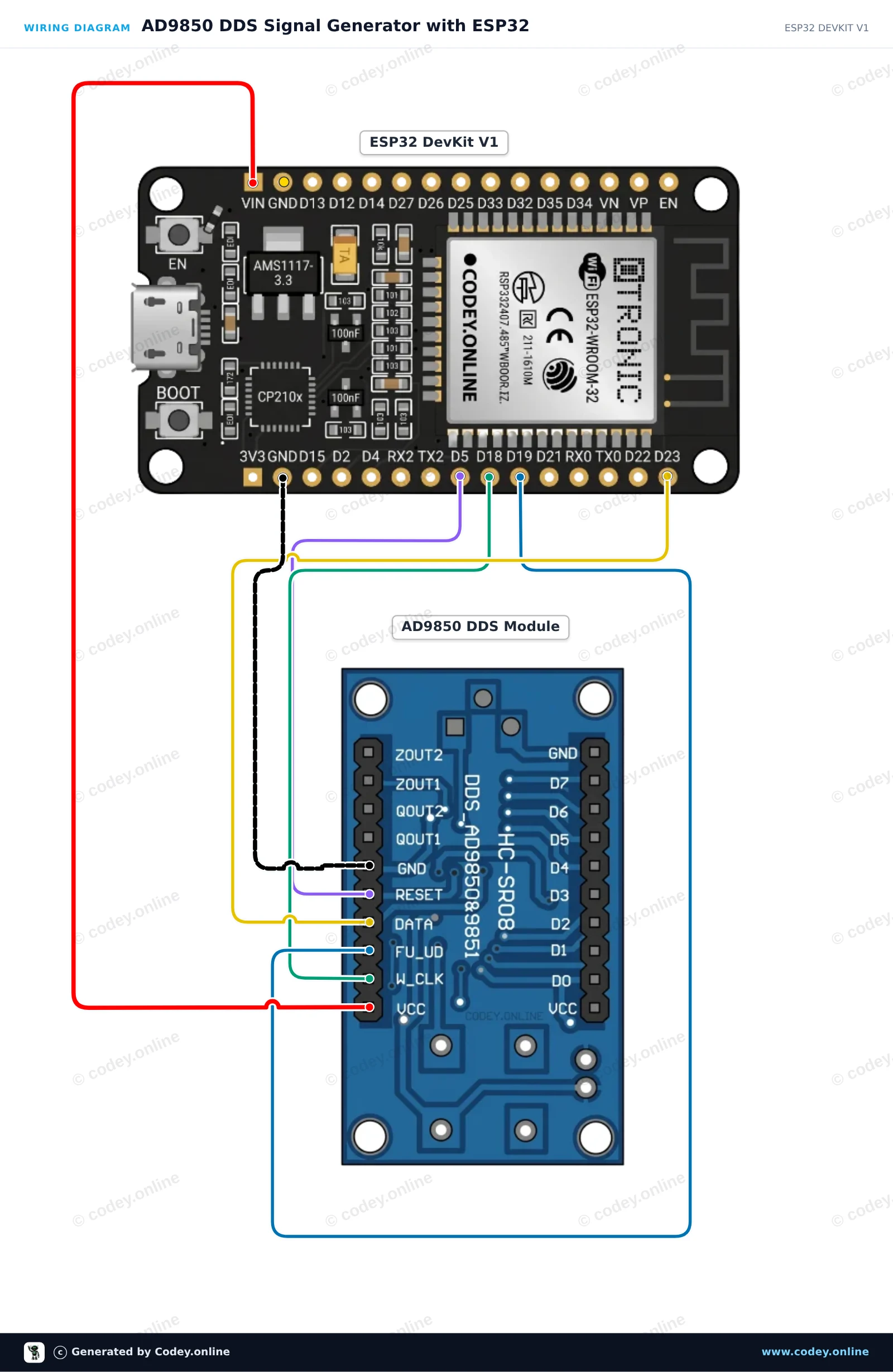
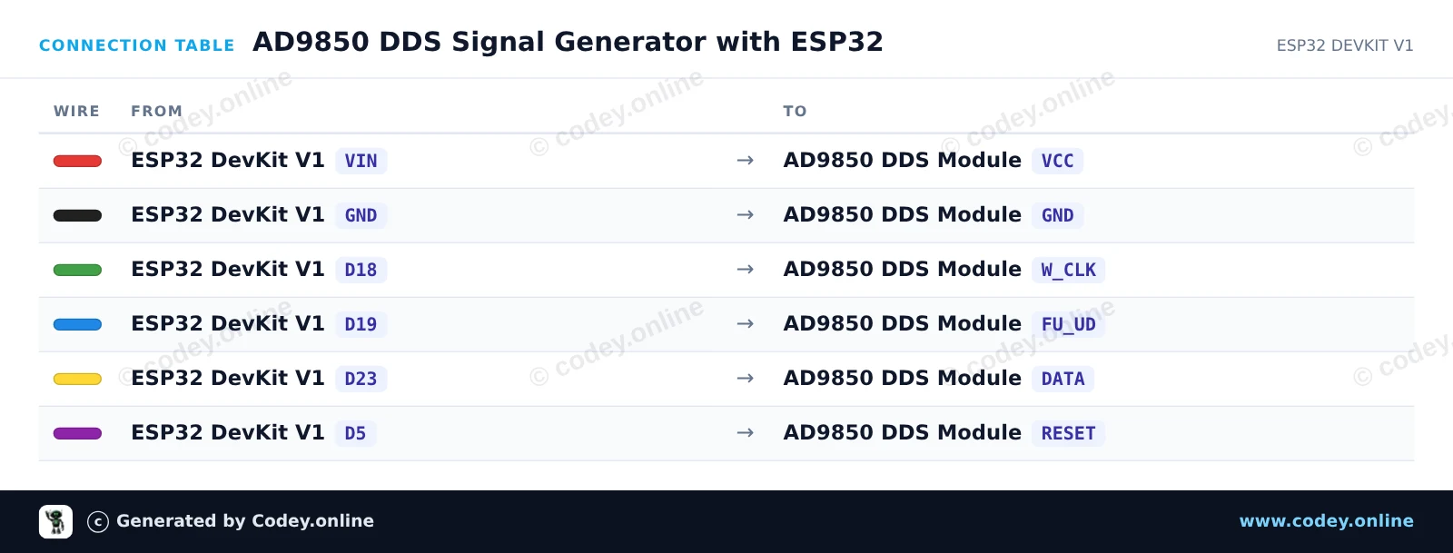
Så här kopplar du AD9850 DDS-signalgenerator-modul till en Arduino UNO eller ESP32, med ett exempelsketch som du kan ladda upp direkt.
This project controls an AD9850 DDS module via a 4-wire serial interface to generate precise sine and square wave frequencies. The Arduino initializes the DDS module and periodically switches the output frequency between 1 kHz, 10 kHz, and 100 kHz. Connect an oscilloscope or frequency counter to ZOUT1 (sine wave) or QOUT1 (square wave) to inspect the output signal.
/*
 * ==================================================================
 *  Generated by Codey.online  —  https://www.codey.online
 * ==================================================================
 *  Project   : AD9850 DDS Sine & Square Wave Generator
 *  Board     : Arduino UNO (arduino:avr:uno)
 *  Parts     : AD9850 DDS Signal Generator Module
 *  Libraries : none (built-in)
 *
 *  Codey Online is an AI-powered browser IDE for Arduino and ESP32.
 *  Describe your project and Codey writes the code, draws the wiring
 *  diagram and uploads it to your board, straight from the browser.
 *  This code is free to use, modify and share, without warranty.
 * ==================================================================
 */

const int PIN_W_CLK = 8;
const int PIN_FQ_UD = 9;   // Labeled FU_UD on module
const int PIN_DATA  = 10;
const int PIN_RESET = 11;

const unsigned long AD9850_REF_CLOCK = 125000000UL; // 125 MHz reference oscillator

void pulsePin(int pin) {
  digitalWrite(pin, HIGH);
  delayMicroseconds(1);
  digitalWrite(pin, LOW);
  delayMicroseconds(1);
}

void ad9850Reset() {
  digitalWrite(PIN_RESET, HIGH);
  delayMicroseconds(1);
  digitalWrite(PIN_RESET, LOW);
  delayMicroseconds(1);
  pulsePin(PIN_W_CLK);
  pulsePin(PIN_FQ_UD);
}

void ad9850SetFrequency(double freqHz) {
  // Calculate 32-bit tuning word: (freq * 2^32) / ReferenceClock
  uint32_t tuningWord = (uint32_t)((freqHz * 4294967296.0) / (double)AD9850_REF_CLOCK);

  // Transmit 32-bit frequency tuning word (LSB first)
  for (int i = 0; i < 32; i++) {
    digitalWrite(PIN_DATA, (tuningWord >> i) & 0x01);
    pulsePin(PIN_W_CLK);
  }

  // Transmit 8 control/phase bits (all 0 for normal operation)
  for (int i = 0; i < 8; i++) {
    digitalWrite(PIN_DATA, LOW);
    pulsePin(PIN_W_CLK);
  }

  // Latch the updated frequency into the DDS core
  pulsePin(PIN_FQ_UD);
}

void setup() {
  pinMode(PIN_W_CLK, OUTPUT);
  pinMode(PIN_FQ_UD, OUTPUT);
  pinMode(PIN_DATA, OUTPUT);
  pinMode(PIN_RESET, OUTPUT);

  digitalWrite(PIN_W_CLK, LOW);
  digitalWrite(PIN_FQ_UD, LOW);
  digitalWrite(PIN_DATA, LOW);
  digitalWrite(PIN_RESET, LOW);

  Serial.begin(115200);
  while (!Serial) {
    ;
  }

  Serial.println(F("AD9850 DDS Generator Initialized"));
  ad9850Reset();
}

void loop() {
  const double testFrequencies[] = {1000.0, 10000.0, 100000.0};

  for (int i = 0; i < 3; i++) {
    double freq = testFrequencies[i];
    ad9850SetFrequency(freq);
    Serial.print(F("Output frequency set to: "));
    Serial.print(freq);
    Serial.println(F(" Hz"));
    delay(3000);
  }
}Wiring diagram and example code generated by Codey.online — https://www.codey.online
This project generates precise sine and square wave signals using the AD9850 DDS module controlled by an ESP32. The sketch steps through a sequence of frequencies (1 kHz, 10 kHz, 100 kHz, and 1 MHz) every 3 seconds. Connect an oscilloscope or frequency counter to ZOUT1 for a sine wave or QOUT1 for a square wave output.
/*
 * ==================================================================
 *  Generated by Codey.online  —  https://www.codey.online
 * ==================================================================
 *  Project   : AD9850 DDS Signal Generator with ESP32
 *  Board     : ESP32 DEVKIT V1 (esp32:esp32:esp32doit-devkit-v1)
 *  Parts     : AD9850 DDS Signal Generator Module
 *  Libraries : none (built-in)
 *
 *  Codey Online is an AI-powered browser IDE for Arduino and ESP32.
 *  Describe your project and Codey writes the code, draws the wiring
 *  diagram and uploads it to your board, straight from the browser.
 *  This code is free to use, modify and share, without warranty.
 * ==================================================================
 */

// AD9850 DDS Signal Generator Demo on ESP32
const int W_CLK_PIN = 18;
const int FU_UD_PIN = 19;
const int DATA_PIN  = 23;
const int RESET_PIN = 5;

// 125 MHz reference clock crystal on board
const double REF_CLK = 125000000.0;

const double testFrequencies[] = {1000.0, 10000.0, 100000.0, 1000000.0};
const int numFrequencies = sizeof(testFrequencies) / sizeof(testFrequencies[0]);
int currentFreqIndex = 0;

void pulseHigh(int pin) {
  digitalWrite(pin, HIGH);
  delayMicroseconds(1);
  digitalWrite(pin, LOW);
  delayMicroseconds(1);
}

void resetAD9850() {
  pulseHigh(RESET_PIN);
  pulseHigh(W_CLK_PIN);
  pulseHigh(FU_UD_PIN); // Enable serial load mode
}

void sendFrequency(double frequency) {
  uint32_t tuningWord = (uint32_t)((frequency * 4294967296.0) / REF_CLK);

  // Send 32-bit frequency tuning word (LSB first)
  for (int i = 0; i < 32; i++) {
    digitalWrite(DATA_PIN, (tuningWord >> i) & 0x01);
    pulseHigh(W_CLK_PIN);
  }

  // Send 8 control/phase bits (0x00 for 0 phase offset)
  for (int i = 0; i < 8; i++) {
    digitalWrite(DATA_PIN, LOW);
    pulseHigh(W_CLK_PIN);
  }

  // Latch new frequency to output
  pulseHigh(FU_UD_PIN);
}

void setup() {
  Serial.begin(115200);
  delay(500);
  Serial.println("AD9850 DDS Signal Generator Initializing...");

  pinMode(W_CLK_PIN, OUTPUT);
  pinMode(FU_UD_PIN, OUTPUT);
  pinMode(DATA_PIN,  OUTPUT);
  pinMode(RESET_PIN, OUTPUT);

  digitalWrite(W_CLK_PIN, LOW);
  digitalWrite(FU_UD_PIN, LOW);
  digitalWrite(DATA_PIN,  LOW);
  digitalWrite(RESET_PIN, LOW);

  resetAD9850();
  Serial.println("AD9850 ready!");
}

void loop() {
  double freq = testFrequencies[currentFreqIndex];
  sendFrequency(freq);

  Serial.print("Output frequency set to: ");
  Serial.print(freq, 0);
  Serial.println(" Hz");

  currentFreqIndex = (currentFreqIndex + 1) % numFrequencies;
  delay(3000);
}Wiring diagram and example code generated by Codey.online — https://www.codey.online





 English
  Nederlands
  Frans
Frans  Deutsch
  Italiano
  Español
  Suomi
Suomi  Polski
  Dansk
Dansk  Ελληνικά
  Български
  Čeština
  Hrvatski
  Aileen