SKU: OT5003 Artikelnummer: AA119 EAN: 8720618231512

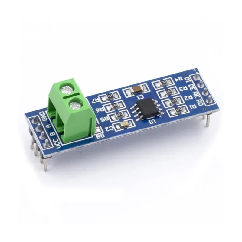
MAX485-modul med MAX485-chipen med låg strömförbrukning för RS-485-kommunikation. RS485 används för seriell kommunikation över längre avstånd än direkt RS232 eller TTL och stöder flera enheter på samma buss.
MAX485-modulens specifikationer:
– Fungerar på: 5V.
– Inbyggd anslutning för RS-485-ledningar.
– Mått: 44mm x 14mm.
Mått
Längd: 4,39cm
Bredd: 1,41cm
Höjd: 1,89cm
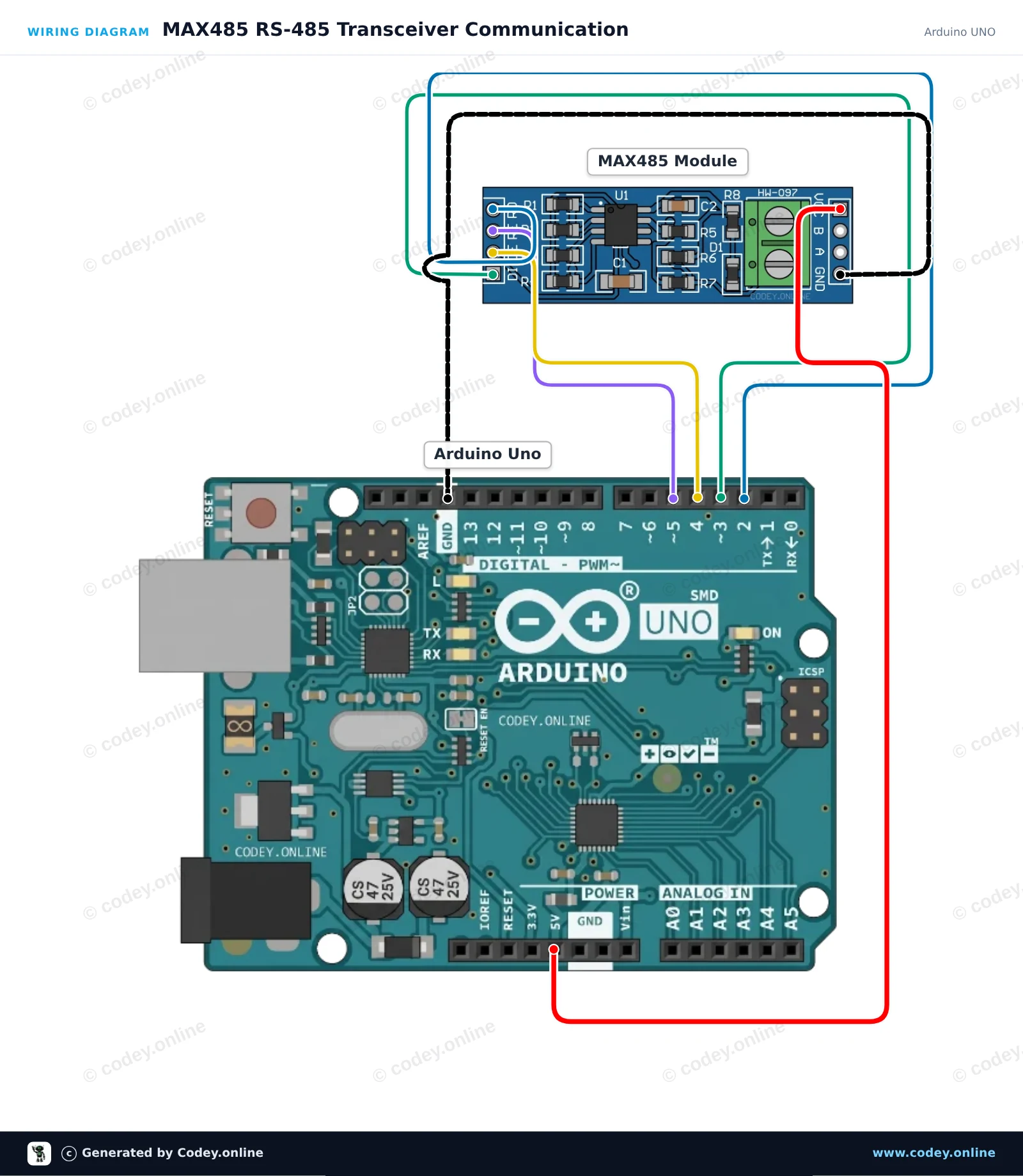
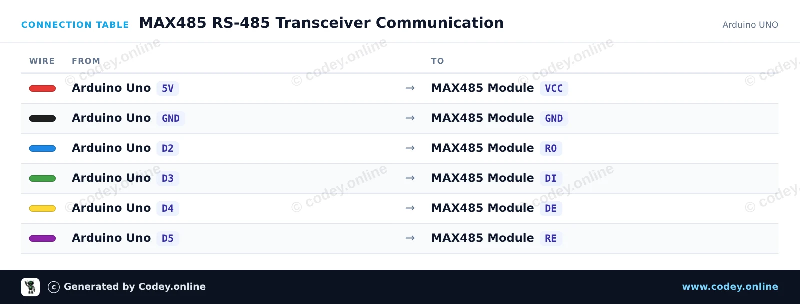
Så här kopplar du MAX485 TTL till RS485-omvandlarmodul till en Arduino UNO eller ESP32, med ett exempelsketch som du kan ladda upp direkt.
This circuit interfaces an Arduino Uno with an RS-485 differential bus using the MAX485 transceiver. SoftwareSerial handles communication with the module, while digital pins control transmit and receive modes. Any message typed into the Serial Monitor is transmitted over RS-485, and incoming bus data is printed to the screen.
/*
 * ==================================================================
 *  Generated by Codey.online  —  https://www.codey.online
 * ==================================================================
 *  Project   : MAX485 RS-485 Transceiver Communication
 *  Board     : Arduino UNO (arduino:avr:uno)
 *  Parts     : MAX485 TTL to RS485 Converter Module
 *  Libraries : none (built-in)
 *
 *  Codey Online is an AI-powered browser IDE for Arduino and ESP32.
 *  Describe your project and Codey writes the code, draws the wiring
 *  diagram and uploads it to your board, straight from the browser.
 *  This code is free to use, modify and share, without warranty.
 * ==================================================================
 */

#include <SoftwareSerial.h>

const byte PIN_RO = 2;   // Receiver Out (RX)
const byte PIN_DI = 3;   // Driver In (TX)
const byte PIN_DE = 4;   // Driver Enable (Active HIGH)
const byte PIN_RE = 5;   // Receiver Enable (Active LOW)

SoftwareSerial rs485(PIN_RO, PIN_DI);

unsigned long lastSend = 0;
int packetCount = 0;

void setTransmitMode() {
  digitalWrite(PIN_RE, HIGH); // Disable receiver
  digitalWrite(PIN_DE, HIGH); // Enable driver
  delayMicroseconds(50);
}

void setReceiveMode() {
  digitalWrite(PIN_DE, LOW);  // Disable driver
  digitalWrite(PIN_RE, LOW);  // Enable receiver
  delayMicroseconds(50);
}

void rs485Send(const String &msg) {
  setTransmitMode();
  rs485.println(msg);
  rs485.flush();
  setReceiveMode();
}

void setup() {
  pinMode(PIN_DE, OUTPUT);
  pinMode(PIN_RE, OUTPUT);
  setReceiveMode();

  Serial.begin(115200);
  rs485.begin(9600);

  Serial.println(F("MAX485 RS-485 Transceiver Demo"));
  Serial.println(F("Type a message and press Enter to send over RS-485."));
}

void loop() {
  // Forward incoming Serial Monitor input to RS-485
  if (Serial.available()) {
    String input = Serial.readStringUntil('\n');
    input.trim();
    if (input.length() > 0) {
      Serial.print(F("Sending: "));
      Serial.println(input);
      rs485Send(input);
    }
  }

  // Forward received RS-485 data to Serial Monitor
  if (rs485.available()) {
    Serial.print(F("Received: "));
    while (rs485.available()) {
      char c = (char)rs485.read();
      Serial.print(c);
      delay(2);
    }
    Serial.println();
  }

  // Automatically send a heartbeat packet every 5 seconds
  if (millis() - lastSend >= 5000) {
    lastSend = millis();
    packetCount++;
    String packet = "Ping #" + String(packetCount);
    Serial.print(F("Auto-transmitting: "));
    Serial.println(packet);
    rs485Send(packet);
  }
}Wiring diagram and example code generated by Codey.online — https://www.codey.online
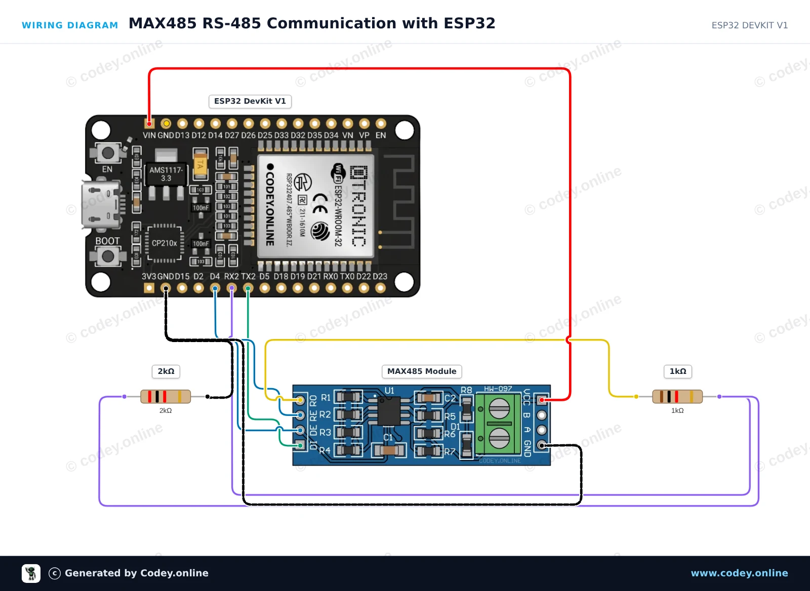
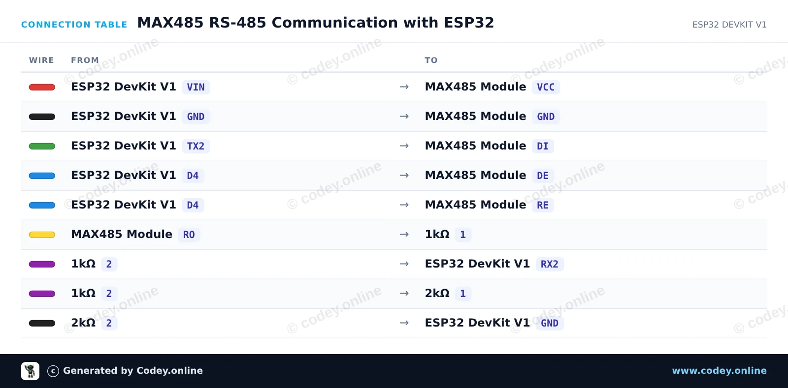
This project demonstrates sending and receiving data over an RS-485 bus using the MAX485 module and ESP32 UART2. The ESP32 switches the DE/RE pins HIGH to transmit a periodic heartbeat message and sets them LOW to listen for incoming RS-485 packets. A simple 1kΩ/2kΩ voltage divider safely drops the 5V TTL output (RO) of the module to 3.3V for the ESP32 RX pin.
/*
 * ==================================================================
 *  Generated by Codey.online  —  https://www.codey.online
 * ==================================================================
 *  Project   : MAX485 RS-485 Communication with ESP32
 *  Board     : ESP32 DEVKIT V1 (esp32:esp32:esp32doit-devkit-v1)
 *  Parts     : MAX485 TTL to RS485 Converter Module
 *  Libraries : none (built-in)
 *
 *  Codey Online is an AI-powered browser IDE for Arduino and ESP32.
 *  Describe your project and Codey writes the code, draws the wiring
 *  diagram and uploads it to your board, straight from the browser.
 *  This code is free to use, modify and share, without warranty.
 * ==================================================================
 */

// MAX485 TTL to RS-485 transceiver demo with ESP32

const int CONTROL_PIN = 4; // Controls DE and RE (HIGH = Transmit, LOW = Receive)
const int RXD2_PIN = 16;
const int TXD2_PIN = 17;

unsigned long lastSendTime = 0;
int messageCount = 0;

void setup() {
  Serial.begin(115200);
  pinMode(CONTROL_PIN, OUTPUT);
  digitalWrite(CONTROL_PIN, LOW); // Start in receive mode

  // Initialize UART2 for RS-485 communication
  Serial2.begin(9600, SERIAL_8N1, RXD2_PIN, TXD2_PIN);

  Serial.println("RS-485 Transceiver Ready");
}

void loop() {
  // Send a message every 2 seconds
  if (millis() - lastSendTime >= 2000) {
    lastSendTime = millis();
    messageCount++;

    // Enable RS-485 transmitter
    digitalWrite(CONTROL_PIN, HIGH);
    delay(10);

    String msg = "Hello from ESP32 #" + String(messageCount);
    Serial2.println(msg);
    Serial2.flush(); // Wait until all outgoing bytes are transmitted

    // Return to receive mode
    digitalWrite(CONTROL_PIN, LOW);

    Serial.print("Sent over RS-485: ");
    Serial.println(msg);
  }

  // Check for incoming RS-485 data
  if (Serial2.available()) {
    Serial.print("Received via RS-485: ");
    while (Serial2.available()) {
      char c = (char)Serial2.read();
      Serial.print(c);
    }
    Serial.println();
  }
}Wiring diagram and example code generated by Codey.online — https://www.codey.online





 English
  Nederlands
  Frans
Frans  Deutsch
  Italiano
  Español
  Suomi
Suomi  Polski
  Dansk
Dansk  Ελληνικά
  Български
  Čeština
  Hrvatski
  Aileen