SKU: OT5490 Artikelnummer: XW064 EAN: 8720828223642

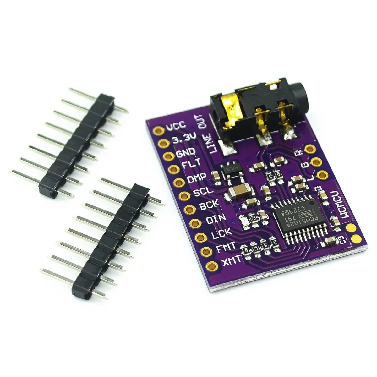
Denna PCM5102A är en Digital-to-Analog Converter (DAC)-modul som främst är avsedd för att omvandla digital ljudinformation till en analog ljudsignal.
Tekniska specifikationer:
Upplösning: PCM5102A stöder ljud med hög upplösning med bitdjup upp till 32 bitar och samplingsfrekvenser upp till 384 kHz.
Direct Path Architecture: En av de unika egenskaperna hos PCM5102A är "Direct Path"-arkitekturen, som gör det möjligt att skicka signalen direkt till utgången utan behov av en extern opamp eller DC-avkopplingskondensator.
Anslutning: PCM5102A använder I2S-gränssnittet, som ofta används i ljudapplikationer för att överföra digital ljudsignal mellan komponenter.
Matningsspänning: 3,3 V till 5 V.
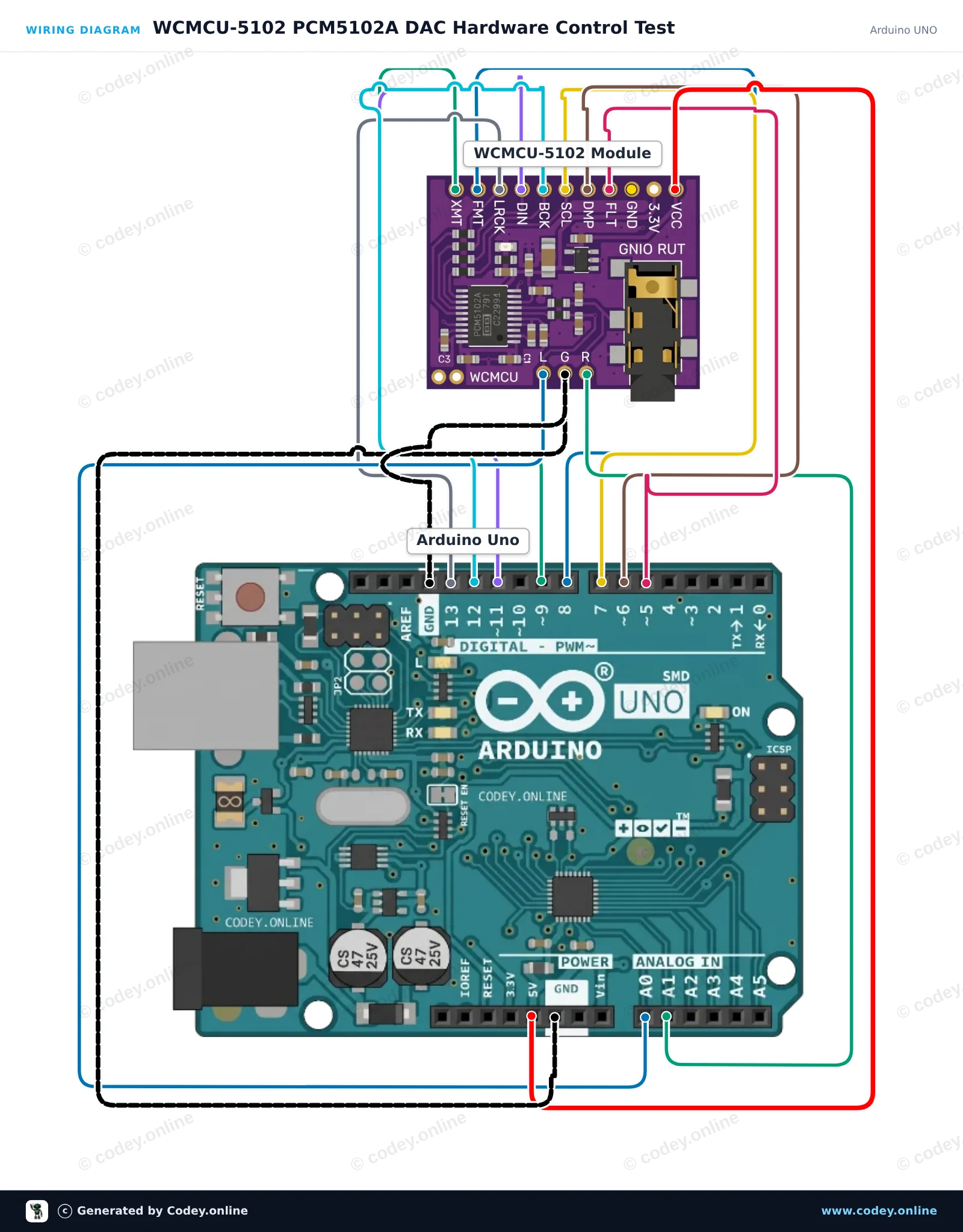
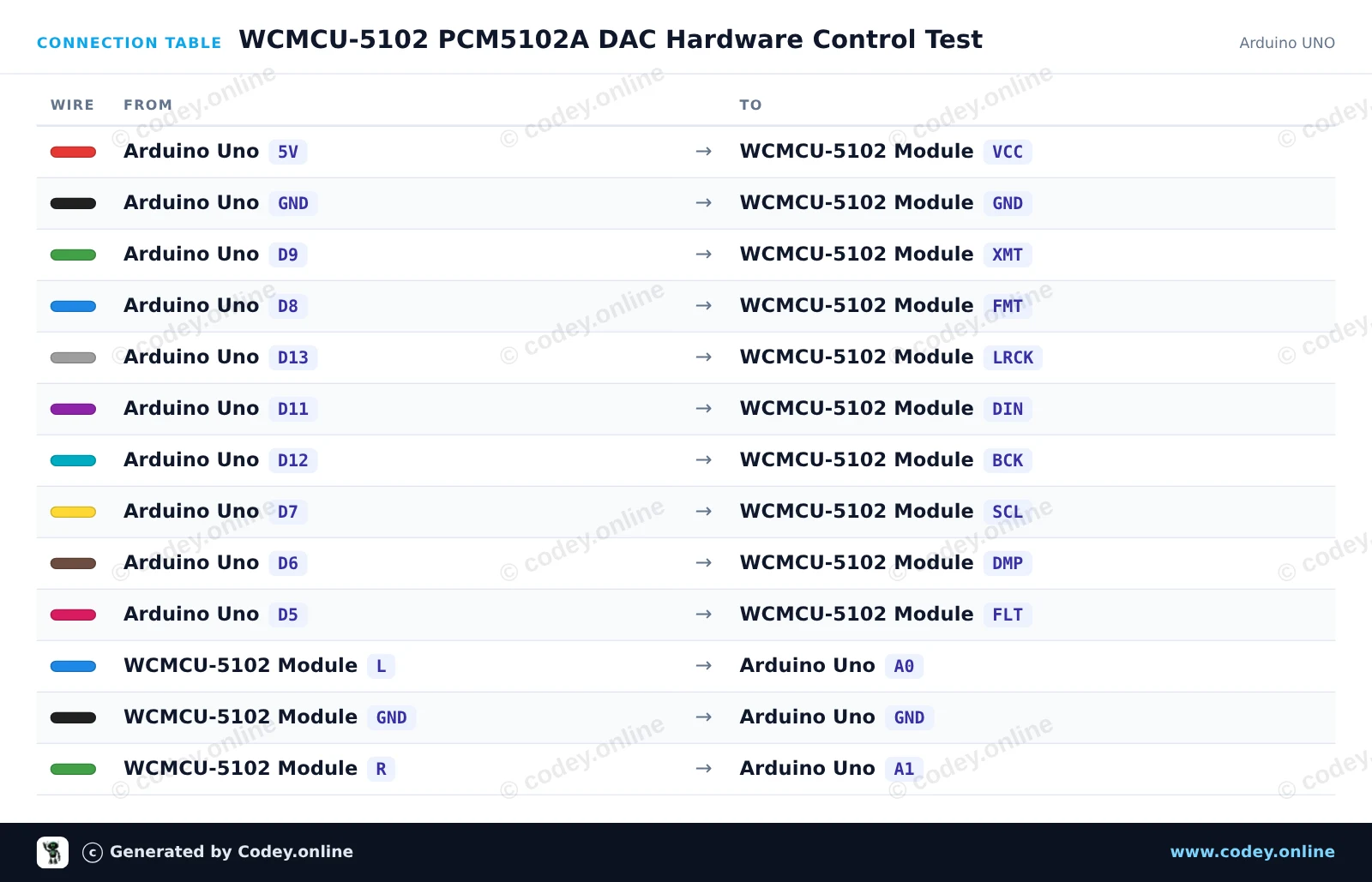
Så här kopplar du WCMCU-5102 modul stereo DAC digital till analog omvandlare till en Arduino UNO eller ESP32, med ett exempelsketch som du kan ladda upp direkt.
This example demonstrates how to power and configure the PCM5102A DAC module with an Arduino Uno. The sketch sets the hardware configuration pins (mute, format, system clock, de-emphasis, and filter) and reports module status over the Serial Monitor. Note that the analog audio output is line-level and should be connected to headphones or an amplifier, never directly to a speaker.
/*
 * ==================================================================
 *  Generated by Codey.online  —  https://www.codey.online
 * ==================================================================
 *  Project   : WCMCU-5102 PCM5102A DAC Hardware Control Test
 *  Board     : Arduino UNO (arduino:avr:uno)
 *  Parts     : WCMCU-5102 module
 *  Libraries : none (built-in)
 *
 *  Codey Online is an AI-powered browser IDE for Arduino and ESP32.
 *  Describe your project and Codey writes the code, draws the wiring
 *  diagram and uploads it to your board, straight from the browser.
 *  This code is free to use, modify and share, without warranty.
 * ==================================================================
 */

// WCMCU-5102 (PCM5102A) DAC Module Control Example
// Configures hardware control pins and toggles the unmute (XMT) signal.

const int PIN_XMT = 9;  // High = Unmute, Low = Soft mute
const int PIN_FMT = 8;  // Low = I2S format
const int PIN_SCL = 7;  // Low = Internal SCK generation
const int PIN_DMP = 6;  // Low = De-emphasis off
const int PIN_FLT = 5;  // Low = Normal latency filter

void setup() {
  Serial.begin(115200);
  while (!Serial);

  pinMode(PIN_XMT, OUTPUT);
  pinMode(PIN_FMT, OUTPUT);
  pinMode(PIN_SCL, OUTPUT);
  pinMode(PIN_DMP, OUTPUT);
  pinMode(PIN_FLT, OUTPUT);

  // Configure default PCM5102A operating modes
  digitalWrite(PIN_FMT, LOW);  // Set standard I2S format
  digitalWrite(PIN_SCL, LOW);  // Generate system clock internally
  digitalWrite(PIN_DMP, LOW);  // Disable de-emphasis filter
  digitalWrite(PIN_FLT, LOW);  // Normal latency filter
  digitalWrite(PIN_XMT, HIGH); // Unmute DAC output

  Serial.println(F("WCMCU-5102 DAC Initialized"));
  Serial.println(F("Configuration: I2S format, internal SCK, unmute active."));
  Serial.println(F("Note: Connect line outputs (L/R) to an amplifier or headphones."));
}

void loop() {
  // Periodic status display
  Serial.println(F("PCM5102A module active and unmuted."));
  delay(2000);
}Wiring diagram and example code generated by Codey.online — https://www.codey.online
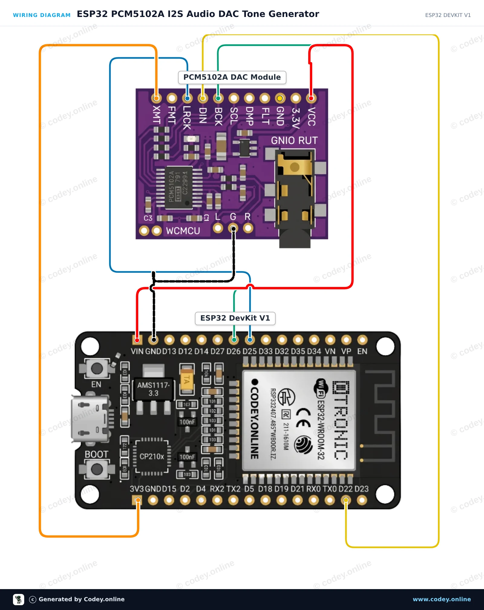
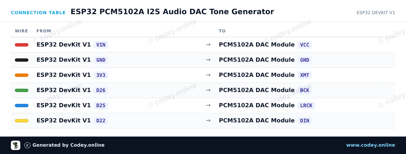
This project connects the ESP32 to a PCM5102A stereo DAC via the I2S digital audio interface to generate a crystal-clear 440 Hz test tone. Plug standard 3.5mm headphones or a line-level amplifier into the audio jack to hear the stereo output. The sketch synthesizes a clean 16-bit sine wave at a 44.1 kHz sample rate using the hardware I2S peripheral.
/*
 * ==================================================================
 *  Generated by Codey.online  —  https://www.codey.online
 * ==================================================================
 *  Project   : ESP32 PCM5102A I2S Audio DAC Tone Generator
 *  Board     : ESP32 DEVKIT V1 (esp32:esp32:esp32doit-devkit-v1)
 *  Parts     : WCMCU-5102 module
 *  Libraries : none (built-in)
 *
 *  Codey Online is an AI-powered browser IDE for Arduino and ESP32.
 *  Describe your project and Codey writes the code, draws the wiring
 *  diagram and uploads it to your board, straight from the browser.
 *  This code is free to use, modify and share, without warranty.
 * ==================================================================
 */

#include <Arduino.h>
#include "driver/i2s.h"
#include <math.h>

#define I2S_BCK_PIN   26
#define I2S_LRCK_PIN  25
#define I2S_DATA_PIN  22

const int SAMPLE_RATE = 44100;
const int TABLE_SIZE  = 128;
int16_t sineTable[TABLE_SIZE];

void setup() {
  Serial.begin(115200);
  Serial.println("ESP32 PCM5102A Audio Test");

  // Generate one period of a sine wave in a lookup table
  for (int i = 0; i < TABLE_SIZE; i++) {
    sineTable[i] = (int16_t)(sin(2.0 * PI * i / TABLE_SIZE) * 10000);
  }

  // Configure I2S peripheral
  i2s_config_t i2s_config = {
    .mode = (i2s_mode_t)(I2S_MODE_MASTER | I2S_MODE_TX),
    .sample_rate = SAMPLE_RATE,
    .bits_per_sample = I2S_BITS_PER_SAMPLE_16BIT,
    .channel_format = I2S_CHANNEL_FMT_RIGHT_LEFT,
    .communication_format = I2S_COMM_FORMAT_STAND_I2S,
    .intr_alloc_flags = ESP_INTR_FLAG_LEVEL1,
    .dma_buf_count = 8,
    .dma_buf_len = 64,
    .use_apll = false,
    .tx_desc_auto_clear = true
  };

  i2s_pin_config_t pin_config = {
    .bck_io_num = I2S_BCK_PIN,
    .ws_io_num = I2S_LRCK_PIN,
    .data_out_num = I2S_DATA_PIN,
    .data_in_num = I2S_PIN_NO_CHANGE
  };

  i2s_driver_install(I2S_NUM_0, &i2s_config, 0, NULL);
  i2s_set_pin(I2S_NUM_0, &pin_config);

  Serial.println("Playing continuous 440 Hz stereo tone...");
}

void loop() {
  size_t bytesWritten = 0;
  // Stream stereo samples (left and right channels)
  for (int i = 0; i < TABLE_SIZE; i++) {
    int16_t stereoSample[2] = { sineTable[i], sineTable[i] };
    i2s_write(I2S_NUM_0, stereoSample, sizeof(stereoSample), &bytesWritten, portMAX_DELAY);
  }
}Wiring diagram and example code generated by Codey.online — https://www.codey.online





 English
  Nederlands
  Frans
Frans  Deutsch
  Italiano
  Español
  Suomi
Suomi  Polski
  Dansk
Dansk  Ελληνικά
  Български
  Čeština
  Hrvatski
  Aileen