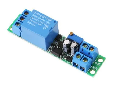
SKU: OT3260 Artikelnummer: NA445 EAN: 8720618231529

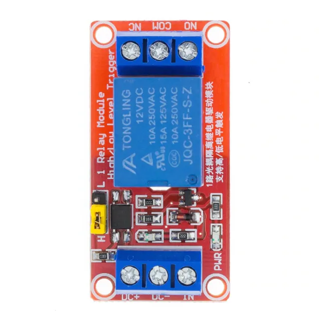
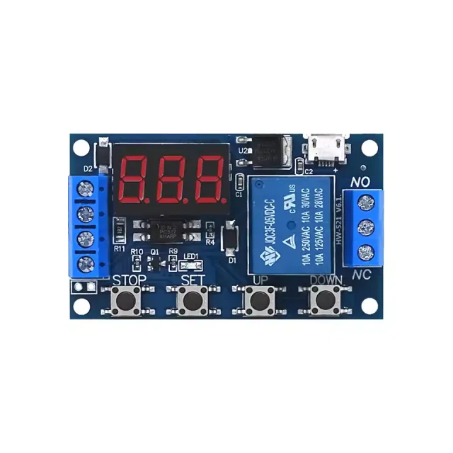
Denna tidsfördröjda relämodul fungerar på 12V och kan ställas in med hjälp av skruvmotståndet.
Driftspänning: DC 12V
Strömförbrukning (när den är aktiverad): ~46mA
Maximal spänning genom reläet: 30VDC eller 250VAC
Maximal ström genom reläet: 10A
Justerbar fördröjning mellan 0.1 och 25 sekunder
För instruktioner och ett kopplingsschema har vi OTRONIC Snabbstartsguide för 12V justerbar tidsfördröjningsrelämodul tillgänglig för dig.
Instruktioner:
Denna OTRONIC® justerbara tidsfördröjningsrelämodul har en justerbar fördröjning för att slå från (falla bort).
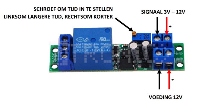
Testa reläet
Du kan testa reläets inställda tid utan extern styrning.
Anslut 12V-strömförsörjning till VCC och GND (strömförsörjning). Utan signal kommer reläet att utföra tidsfördröjningen en gång.
Du kan höra detta genom reläets klick.
Använd skruvmotståndet för att justera tiden. Vrid moturs för längre tid och medurs
för kortare tid.
OBS: Det krävs flera varv på skruven för att justera tiden.
Mått
Längd: 6,68cm
Bredd: 1,6cm
Höjd: 1,68cm
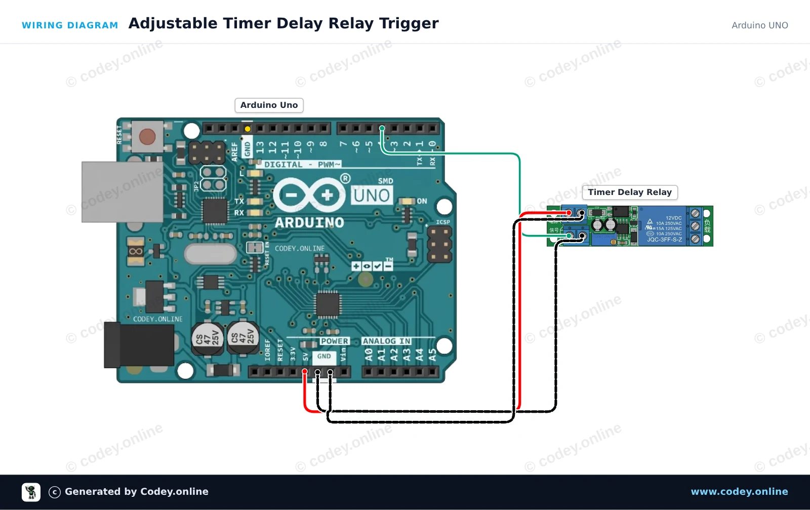
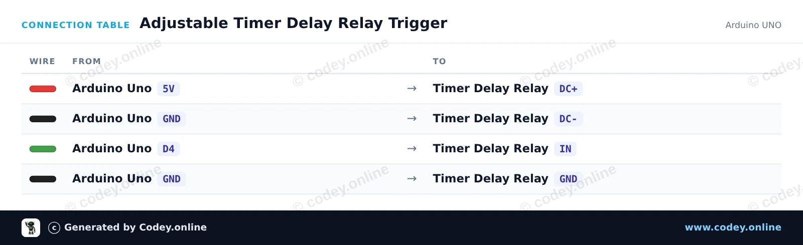
Så här kopplar du 12V justerbar tidsfördröjningsrelämodul till en Arduino UNO eller ESP32, med ett exempelsketch som du kan ladda upp direkt.
This project demonstrates how to trigger an adjustable timer delay relay module using an Arduino Uno. The Arduino sends a short pulse from digital pin 4 to the IN trigger pin, activating the onboard timer delay cycle. Adjust the potentiometer on the relay module to change the duration of the relay activation.
/*
 * ==================================================================
 *  Generated by Codey.online  —  https://www.codey.online
 * ==================================================================
 *  Project   : Adjustable Timer Delay Relay Trigger
 *  Board     : Arduino UNO (arduino:avr:uno)
 *  Parts     : DC 12V adjustable timer delay, time delay relay turn off switch module time relay time switch 0~25sec for smart home, automatic control
 *  Libraries : none (built-in)
 *
 *  Codey Online is an AI-powered browser IDE for Arduino and ESP32.
 *  Describe your project and Codey writes the code, draws the wiring
 *  diagram and uploads it to your board, straight from the browser.
 *  This code is free to use, modify and share, without warranty.
 * ==================================================================
 */

// Timer Delay Relay Module Demo
// Sends a trigger pulse to start the module's countdown delay.

const int triggerPin = 4;

void setup() {
  pinMode(triggerPin, OUTPUT);
  digitalWrite(triggerPin, LOW);

  Serial.begin(115200);
  Serial.println(F("Timer Delay Relay Demo Initialized."));
}

void loop() {
  Serial.println(F("Triggering relay delay cycle..."));

  // Send a 200 ms HIGH pulse to trigger the module
  digitalWrite(triggerPin, HIGH);
  delay(200);
  digitalWrite(triggerPin, LOW);

  Serial.println(F("Trigger sent. Waiting for delay cycle to complete..."));

  // Wait 10 seconds before triggering the next cycle
  delay(10000);
}Wiring diagram and example code generated by Codey.online — https://www.codey.online
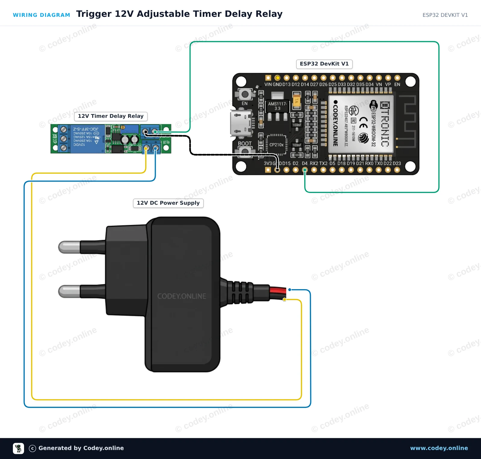
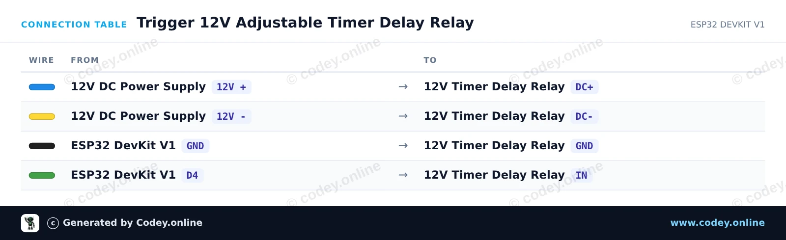
This project demonstrates triggering an adjustable 12V time delay relay module using an ESP32. The ESP32 sends a short trigger pulse to start the countdown, and the relay stays energized for the duration set by the onboard potentiometer (0 to 25 seconds).
/*
 * ==================================================================
 *  Generated by Codey.online  —  https://www.codey.online
 * ==================================================================
 *  Project   : Trigger 12V Adjustable Timer Delay Relay
 *  Board     : ESP32 DEVKIT V1 (esp32:esp32:esp32doit-devkit-v1)
 *  Parts     : DC 12V adjustable timer delay, time delay relay turn off switch module time relay time switch 0~25sec for smart home, automatic control
 *  Libraries : none (built-in)
 *
 *  Codey Online is an AI-powered browser IDE for Arduino and ESP32.
 *  Describe your project and Codey writes the code, draws the wiring
 *  diagram and uploads it to your board, straight from the browser.
 *  This code is free to use, modify and share, without warranty.
 * ==================================================================
 */

// Pin connected to the IN trigger pin of the timer relay module
const int TRIGGER_PIN = 4;

void setup() {
  Serial.begin(115200);
  pinMode(TRIGGER_PIN, OUTPUT);
  digitalWrite(TRIGGER_PIN, LOW);

  Serial.println("ESP32 12V Timer Delay Relay Module Initialized");
  delay(1000);
}

void loop() {
  Serial.println("Sending trigger pulse...");

  // Send a 200 ms pulse to activate the timer
  digitalWrite(TRIGGER_PIN, HIGH);
  delay(200);
  digitalWrite(TRIGGER_PIN, LOW);

  Serial.println("Triggered! The relay will remain active for the duration set by the potentiometer.");

  // Wait 15 seconds before triggering the next cycle
  delay(15000);
}Wiring diagram and example code generated by Codey.online — https://www.codey.online







 English
  Nederlands
  Frans
Frans  Deutsch
  Italiano
  Español
  Suomi
Suomi  Polski
  Dansk
Dansk  Ελληνικά
  Български
  Čeština
  Hrvatski
  Aileen